|
|
Fiat Tuning |
|
|
Making
the Fiat Blitz Fly……….. Or one man's DIY guide of trying to find an extra hamster power from the air cooled Fiat breathless wonder. Having raced with these engines for a couple of years now, I can say they are remarkably tough. Although a parallel twin has never been a good engine design (It only gains marginally over a single cylinder due to lower piston mass and ability to rev), these engines have some good points. They have strong twin valve springs (that prevent valve bounce), alloy push rods (Less mass than steel), light block alloy and head, and strong valves. Only failures so far have been due to lack of oil (Broken rings) and a dropped valve due to severe over revving with no load. When considering rebuilding a standard engine, spare parts can present a problem. Parts are available from Fiat, but at excessive expense considering the simple nature of the engine. There are a good supply of parts from Europe, and Middle Barton Garage in Oxfordshire import these parts (01869 340285) .They also supply Abarth tuning parts. It is for instance cheaper to buy a complete new piston and barrel set from them, than to get oversize pistons from Fiat alone, with the added expense of a re-bore. Also see the links section for parts available. The cars were still produced in Poland until recently, and we have been offered new spares directly. This may become cost effective with Poland joining the EEC, and reducing the export costs. Without spending a fortune on the engine the DIY tuning options are limited. The most fundamental problems are the crank strength and support. The standard engine is limited to maximum power at 4700 rpm by its inlet breathing and cam duration. In standard form the crank will take 6500 rpm, but is prone to blowing out the staked in oil blanking plugs that must be carefully checked if rebuilding. I dab extra weld on to be sure.
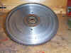
The crank can also whip due to the lack of reinforcement in the crankcase and standard sump. The latter can be reduced by fitting a cast alloy sump that has also the added benefit of holding more oil with greater cooling. Its worth balancing all the engine internals to aid engine life, and as importantly prevent the engine shaking itself instead of putting out energy on the crank. The original Fiat balancing however is pretty good, if no components major components have been changed. Although a parallel twin can never be fully balanced, it does help in getting rid of vibrations in other directions and unbalanced forces on the crank. I used Oselli engine services of Oxford for this work. 01865 248100. Stripping the engineThis engine can be stripped down easily. Parts that are oil stained can be cleaned with Mr Muscle oven cleaner. Leave it to soak for 20 min’s and rinse with water and dry thoroughly. This will remove the black hardened sludge from engine components. (unlike petrol or thinners) Corroded alloy can be cleaned with acid based alloy wheel cleaner. If regrinding the crank oversize bearings are available in .2 mm steps. Speak to Middle Barton. Notes on reassembling the engineA couple of points worth mentioning as they are omitted in the Haynes manual.Firstly clean all the screw threads with cellulose thinners and let them dry. Then Loctite everything on re-assembly. In particular the big end nuts as these have no lock washers. These engines vibrate and will shake anything loose. Make sure you re torque the head nuts after the engine has run for a while as these come very loose as the head and base gaskets compress. Also don't be tempted to use second hand gaskets. The engine has quite high crankcase pressures as both pistons descend at the same time, pressurising the crankcase. This pressure should vent through a one way valve attached to the oil filler, to an oil breather pipe. ANY restriction in this outlet causes the oil to be forced out of the engine past any slightly weak joint. Balancing the engine You can get all the components done professionally, and expect to pay about £150 for this or alternatively some parts can be done at home as below. Con RodsThese have to be balanced end to end and overall. The end to end involves holding the rod in a horizontal plane by passing a pivot through the big end or small end journal and weighing the other end. The heavier rod then has to have metal removed from the spare weight cast as part of the rod at each end to match the lighter rod. This is done for both ends. Once this is done then the overall weights are matched by removing small amounts of metal from the shank of the heavier rod. This can be done at home using accurate cooking scales (down to 1 gram) or postal scales. Make sure you place the end to be measured over the center of the scales for accuracy. CrankshaftThis presents a problem. The technique for balancing a parallel twin engine is to attach a specific weight to the big end journals and then spin the crank. This is to match the combined forces of the piston and rod on the crank. This weight figure is worked out by the manufactures and is the "factor of balance" and s is 89%. By this I understand that when spinning the crank to balance it you need this figure to work out how much you add to the big end journals to counteract the balance weight on the crank. I think you add 11% of the weight of the rods pistons pins etc to the journals but your balancing firm will know this. Unfortunately this figure is not readily available from Fiat, as they do not balance the crank in this fashion so I have not been able to balance it beyond the factory set up. I have since been told that this can be done by AES. See links FlywheelThese come in two sizes. The earlier has a ring gear thickness of 12mm, and the later about 10mm. When used in the Blitz both types can be severely reduced in weight by removing the entire additional ring on the back and skimming the flywheel down to a minimum of about 7mm thick. (Leave the ring gear) This will reduce the weight by about 60% and greatly improves the pickup, and reduces the load on the gearbox when changing down. The area where the clutch bolts on needs more thickness for the dowel pins, so a thicker band needs leaving at this point. (10mm thick) Also do not remove too much near the center as this dissipates heat from the clutch, or obviously where it bolts to the crank. Note that this machining will remove any effective balancing previously done on the flywheel at the factory. The clutch diaphragm plate then needs fitting and clearly marked to align it in future. Some tuners do not recommend too much to be removed as more weight helps reduce the crank vibration, but so far so good ! |
 |
The exhaust port opened up. Exhaust ports can be polished for the ultimate flow. |
NOTE, A well modified single port head with a fast road cam will work just as well as the twin port design. The twin port may flow slightly better with a more radical cam, but the standard crank will not take the higher RPM needed.
 |
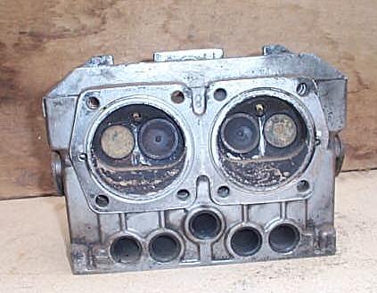
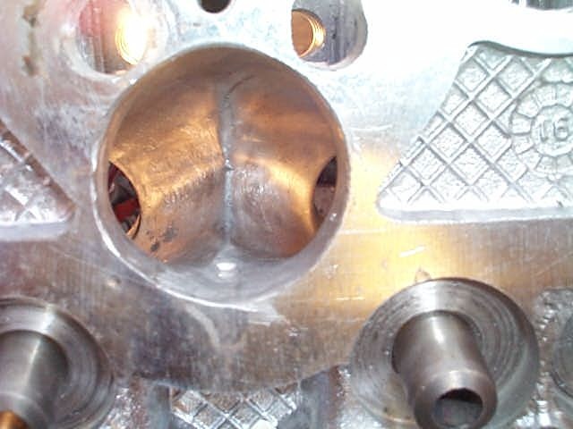
Twin port head. Two head will studs project into the inlet ports and require cutting down and rethreading. |
 |
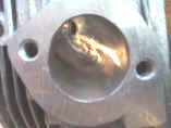
Combustion chamber. Check head for cracking between valve seats. |
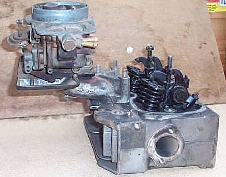 |
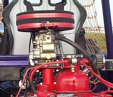
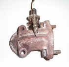
Standard Panda 30 Carb' and manifold |
 |
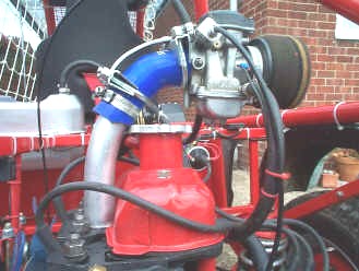
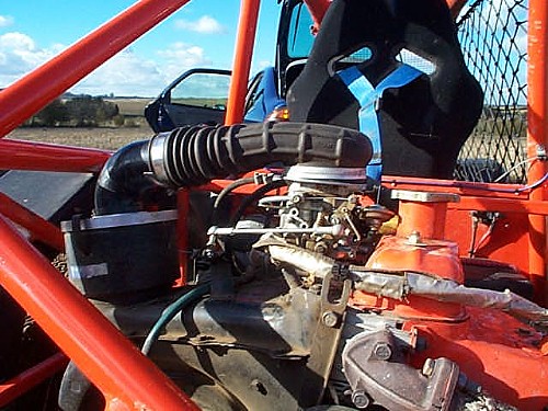
The angle of the carb' is not ideal when fitted to the 126 engine. It is best to mount the carb'' vertically by inserting angled spacers or machining the manifold. Note the short additional push rod tubes and the extra casting at the base of the head. |
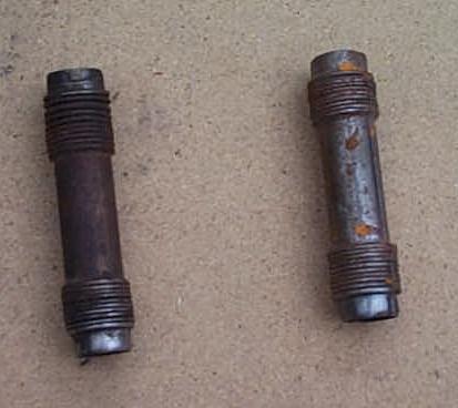 |
Panda 30 push rod tubes. These go between the head and the block. If you are lucky there may be some sealing rings in your 126 gasket kit, as some have the Panda 30 gaskets as well. Make sure you get these tubes, as using the 126 tubes needs some machining work to the head. |
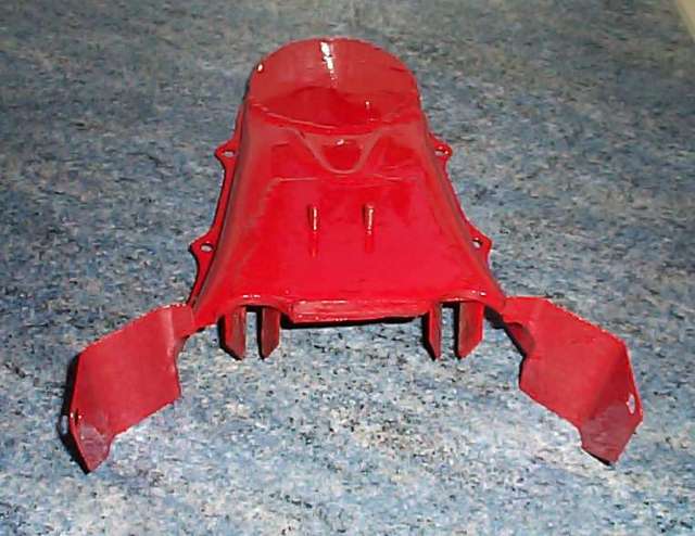 |
Modifying the fan housing requires extra side pieces and cutting back around 1.5cm from around the plug hole cut outs |
 |
The fitted head. Subtle as a brick. |
 |
End on showing the extra metal added to keep the airflow close to the cylinder walls. This head is fitted with an after market manifold and Solex twin port carb'. |
Camshaft - or how to bore your friends at the pub........
The choice of cam can be a little bewildering. At its simplest level, there are two parameters we are interested in, duration and total lift. An inlet valve duration is worked out by firstly the point at which the valve first opens before the piston reaches top dead center. It may seem strange to start to open the valve before the piston can draw air (i.e. its still going upwards), but the majority of the exhaust gas is being pushed through the open exhaust valve at this point. Also you need the inlet valve to be becoming fully open as the piston starts to descend. A typical figure for the valve opening would be 25’ before top dead center. As the valve carries on lifting, it will still reach its maximum lift point somewhere after top dead center, typically 110' as the piston descends. The valve then starts to close, but is still partially open as the piston reaches bottom dead center. As the inlet mixture has been shooting into the piston chamber, it has a high velocity in the inlet manifold, that can still help squeeze a bit more into the chamber even though the piston is starting to move up. This can also be helped by having long inlet manifold tubing so the mixture is being “pushed” by more mixture from behind. It is the number of degrees after bottom dead center that the valve closes is the second figure quoted to work out the duration. A typical value would be 55'. From this it can be seen that compressing the mixture can only start after the inlet valve has closed , so the piston is already part way up the bore before this happens. With increased duration, the engine only becomes efficient when the inlet mixture velocity is high enough to carry on ramming the mixture in at high rev’s. Hence one reason why full race cams ran very badly at low rev’s. This is added to by by both the inlet and exhaust valves being open at the same time with the increased duration (called the overlap) causing poor breathing at low revs. To work out the total duration, you add the two figures together plus 180’ as one figure is before top dead center and the other is after bottom dead center. So for this example we have a value of 25' + 180' +55 = 265'. Reground cams tend to have the same inlet and exhaust valve duration, as it is easier to use the same cam profile on each cam lobe. This may not be the ultimate valve timing for the engine, but as they say you get what you pay for. If a cam has a short duration this allows the engine to be at most efficient at low rpm, leading to an engine that has good torque off the line. The down side is as the rpm rises, the efficiency drops, so the engine starts to feel strangled. The 4700 rpm “brick wall “ reached on an un-tuned 126 engine is only partly cam duration,. (the later 126 cam profile is already quite sporting in comparison to the 500 engine it is based on, and can will perform quite well given better breathing ) but more notably the miserable 22mm choke size used in the standard carb’, combined with reversion problems.
The second parameter is the total valve lift available from the cam. This can be stated in 2 ways, either the actual lift of the cam itself, or the lift of the valve having had the cam lift multiplied by the rocker ratio, as the rocker does not pivot at a central point. This ratio is around 1.5:1 on the 126 engine, so the valve opens 1.5 time more than the cam lift. Simply increasing the cam lift (but not duration) can help increase the engines breathing so the overall torque improves. When regrinding a standard cam, the amount of extra lift is limited by the amount of spare metal on the heal of the cam that can be removed before the cam follower will rub on the shaft of the cam. Even with a cam made from a new billet, cam lift is limited by both the valves springs becoming coil bound and possible valve to piston contact, especially on high compression head. The shape of the lobe is also important so the cam follower can follow the cam profile without excessive wear. A high performance cam will try to use the best of both worlds, with both increased lift and duration. This works well up to a point, but with a regrind, as the duration of the cam increases, the cam lobe tip is ground flatter, (holding the valve open for longer) and even with grinding metal off the cam heal, the lift cannot be increased any further, and may even reduce. On top of this the valve clearances must be increased to allow the cam follower to start to lift the valve at the correct point as the cam starts to lift. The net result is you can loose lift and the engine can become noisy. From my experience the best cam duration is about 270’ for an off road Blitz with a lift of 10.68mm, (like the Piper HR270) when running standard valves and crank shaft together with altered inlet and exhaust system. This makes for a really use-able engine. This cam is normally rated as “fast road “ use. This allows the engine to rev well, whilst maintaining good low speed response. I have also tried the HR285, with a measured 290’ duration, (due to sight machining tolerance variations) but slightly reduced lift of 10.48mm. This has not worked as well as the low end power has dropped off noticeably, and although the engine revs freely to a dangerous 6500 rpm plus (Broken crank time), the car is no quicker overall. As there are a huge number of cam profiles available for this engine, and knowing the lift and duration of a cam is a pre requisite, as simply stating is an “Abarth” profile may not lead to good performance in a given situation. Camshaft design is a bit of a black art, with some out performing others with only very minor change’s. Other factors like compression ratio, exhaust type, inlet port size and length all influence how a given cam will perform. Its also worth bearing in mind that cam durations can be altered considerably by changing the valve clearances.
Cam data for the standard cam, Piper regrinds and AES "Abarth profile". See links for AES contact.
| Inlet Duration | Exhaust duration | Valve Lift mm | |
| Standard Pre 85 | 263' | 263' | 9.3 |
| Standard Post 85 | 251' | 276' | 10.3 |
| Piper HR270 | 270' | 270' | 10.68 |
| Piper HR285 | 290' | 290' | 10.48 |
| AES "Abarth Profile" | 280' | 280' | 11.145 |
It is important to set the cam timing accurately. Simply fitting the cam to the standard sprocket can be as much as 15' off the optimum setting. When you get a new cam there should be a value in crank shaft degrees for the cams maximum valve lift. This means using a dial test indicator on the cam follower and protractor on the crank pulley. As the cam reaches its highest point, there is a null point over several crank degrees. You have to take two values, one as the cam stops lifting, and then as it starts to drop. You then need to take the mid point between these values to work out the cams maximum lift point. This can then be compared to the value supplied with the cam. To adjust it to need to elongate the hole in the cam sprocket where the cam lug locates. You can then turn the cam in relation to the sprocket until the correct timing values can be obtained. It is then necessary to infill the excess hole with weld or chemical metal (bit naughty but a lot quicker !) to stop the cam from moving from this point again. This is a very time consuming process, and needs to be done correctly to get the most from the cam. Unfortunately re cut cams are never as good as ones made from a new billet as the profile tends to be a compromise with what material is available. It is possible to get additional material added to the cam tips before a regrind, but its a matter of cost before using "new billeted" camshafts is more economic. Pattern Abarth cams are also available at reasonable cost . See links section.
 |
A protractor held onto the crank pulley with double sided sticky's and an additional marker point. Align the protractor at 0' at TDC and rotate clockwise until the specified maximum cam lift point is reached. This is likely to be around 103 -110 ' degrees after top dead center for the inlet valve depending on the cam type. Rotate the cam independently of its sprocket to the alignment point. The cam sprocket holes then need elongating so it can be bolted to this new point. A dab of JB weld can be used to infill the elongated holes afterwards to ensure the position does not change once set. |
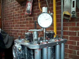 |
A dial test indicator fitted to the head with a bracket. The inlet push rod is a good point to take the reading for maximum cam lift. Maximum point is halfway between the point that the cam stops lifting and then starts to drop. |
As standard the main jet is 1.2mm. This can be found in the float bowl attached to an emulsion tube that then feeds into the venturi with its controlling needle. Unlike an SU the fuel is partially premixed with air via the emulsion tube before its metered by the needle. There is no standard adjustment on the needle height or jet height for the overall fuel /air ratio. As standard the mixture is far too weak and the engine will hardly run, unless the choke is on. With a fuel air meter attached the main jet was opened up in .1 mm steps until reasonable fuelling was reached. This ended up at 1.5mm (funny that!). It is also possible to richen the mixture by putting washers under the main needle to lift it a little.
Inlet Manifold (single port)
Some careful design of the inlet manifold can produce very significant gains in power. The best option is to open up the inlet port to accept a 38mm (external diameter) aluminum tube directly into the inlet port. The overcomes all the various "bolt on " options that have the head fixing nuts getting in the way of the gas flow. This requires the removal of considerable material, and will remove both inlet stud holes. The tube needs to be a tight interference fit, and can be bonded with J B weld, a super tough epoxy resin found in motor shops. Use the 24 hr setting stuff, not the quick version. The point where the single port splits to feed each valve will also need carefully matching to the new enlarged hole. The new tube is very close to the head fixing nuts and so the holes need elongating to allow the studs to be flexed away a little. Final torque down of the head requires a 17mm socket with part cut away to allow it to fit over the nut as its so close to the new tube. Although flexing the studs changes the head loading very slightly, it has not proved a problem
Mounting a bike carb'
Radiator Silicone hose can be used to join the bike carb' onto the new tube. IT IS MOST IMPORTANT that the carb must be isolated from the engine vibration in some way by using rubber mountings. If you don't the vibration from the engine causes the fuel to foam and flood the engine.
This setup below has proved the most effective and reliable after several years trying to get it spot on.
 |
An inlet port opened up to take an aluminum tube directly. Note the head stud holes are elongated to allow the head washers and nut to be fitted by bending the stud slightly. |
 |
Aluminum tube fitted to the head. "J B Weld" epoxy resin from motor shops can be used to hold it in instead of welding as it can easily take the heat. A lot easier than welding. |
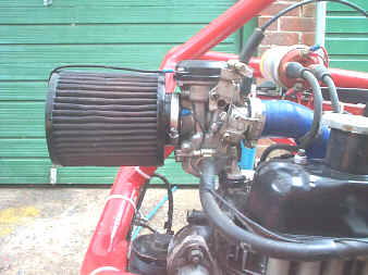 |
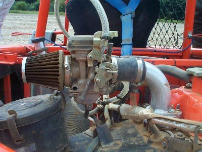
The final setting for a GPZ900 carb' feeding through a silicon rubber radiator hose . The carb' is also supported on a metal bracket and 2 rubber cushions to isolate the vibration. |
Below are some other variations tried.
 |
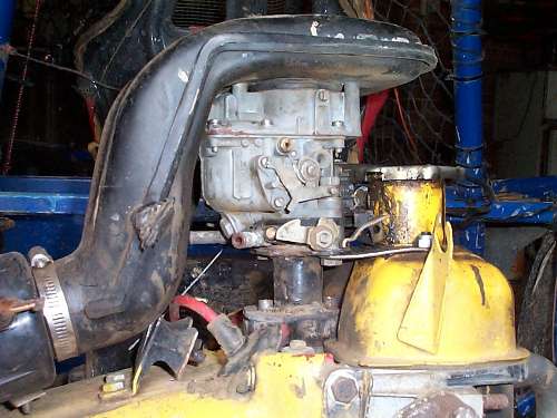
Kawasaki GPZ900 carb' with welded inlet pipe. Did not run well with the engine cold due to the long down tube causing the fuel to condense on the tube. |
 |
Kawasaki KL250 carb' setup made up from various bits. This works very well. |
 |
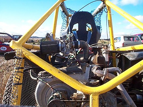
The Australian Predator kit with twin Honda CB250 carb's. Runs best with straight through exhausts! |
 |
Dellorto 34FRD. Works well enough, but lack of vibration isolation causes some problems |
 |
Solex 24mm from Citroen AX. As above. |
 |
Barry's KLR 650 Kawasaki carb'. |
 |
Really neat KLR 250 carb one off set up using some "technocarb" bits that bolts straight on. |
 |
Standard Technocarb twin choke Weber kit from the Panda 30. Has reversion problems and was abandoned. |
The gauge has a display that goes from red (to lean) to green (acceptable range) to red (too rich). An air-cooled engine like the 126 needs some fuel to cool the head so it has to be set to the rich end of the green scale. This is also the best area to set the engine for maximum power. Assuming you have used a two-wire lambda sensor with no heater, you cannot rely on the reading until the sensor gets hot. I put the sensor in the exhaust elbow as it gets hot very quickly, so a reading could be taken within a few minutes. The carburation needs to be somewhere near correct to start with, as if its highly over or under fuelled, the engine will not burn the mixture, and the sensor will not give an out put. As always the vibration from the engine can cause some fuelling glitches that are almost impossible to overcome accurately. The rest is a matter of selecting or drilling suitable jets for the carb' in question, although this is never as simple as it seems !
|
|
|
The standard system is very restrictive, and the cheap big bore systems are not much better. It had been noticed that the gaskets on the cast elbows would constantly blow, so you had to ask where is all this back pressure coming from ? Having had a couple of the big bore systems disintegrate with the vibrations, the internal design could be seen. This basically had the high speed exhaust gas directly hitting the end wall of the silencer before being bounced back though a baffle shield. The problem was it also bounced back straight against the gas flow coming from the engine, a very poor design indeed. The pipes also suffer metal fatigue and constantly needed re-welding. To overcome these problems (and at much lower cost) a small "cherry" bomb silencer was fitted to each exhaust port, leading down the side of the engine. ( bits of the old big bore system where used to join the cherry bomb to the elbow ) Heavy duty brackets where welded to the pipes to allow them to bolt to the engine block, plus and extra tie rod between the two tail pipes to stop any flexing from vibration. This has worked very well indeed with a noticeable gain in power at higher revs, and lifting the exhausts has also improved the ground clearance. Noise is up by 50 %, so not suitable for road use, but great in the middle of no where !
 |
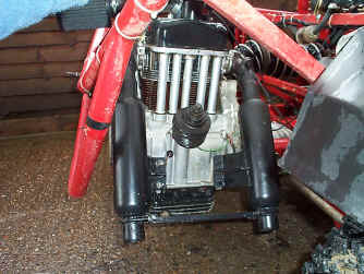 |
2 welded cherry bomb exhausts (£25 each), braced brackets and tie bar. No more exhaust problems and more power! |
The standard system uses a mechanical pump that constantly circulates fuel through the carburetor and back to the tank. This can flood the carburetor as there is no adjustment on the output pressure. I would recommend fitting an electric unit with constant low-pressure output (say 3 psi) such as a Metro or MG Midget unit. These units stop pumping when the float chamber is full so no re-circulation pipe is needed and can cope with full power fuel demand. If fuel leakage from the carb' is a problem, it may be necessary to fit a variable fuel pressure regulator, and reduce the pressure on the float valve. Life is tough for the float valve on a Blitz as the carb' gets shaken so much, so its important to ensure the float and needle are in good condition.
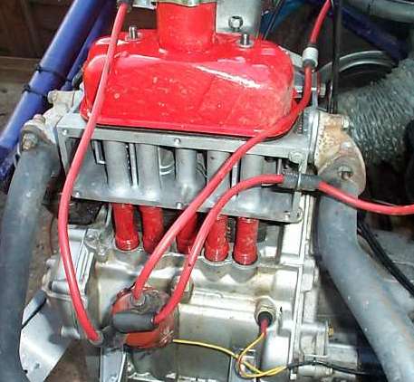
After suffering many years of general ignition unreliability the final set up is to use the wasted spark coil system used on the post 85 engines. This removes the rotor arm that tends to fly apart, and the distributor cap that tends to let dust in. The cap is replaced with a small distributor cover that can be sealed to prevent dust ingress. The standard twin outlet coil tends to burn out if run at 12 volts (I think these should be ballasted to 9 - 10 volts). You can get the coil in both "dry" (like a motorcycle coil) that runs at 10 volts or oil filled (like a conventional car coil) that will run at 12 volts as aftermarket parts. To get a really hot spark get hold of the old style copper cored leads over the more common carbon based leads to maintain spark intensity. (try classic car part suppliers) It is really remarkable the difference, from the normal pale white spark to a really hot blue spark. I have however also experienced problems with copper leads , where the discharge is so intense from the coil, it caused electrical spikes on the 12 volt coil supply and caused the electronics in the fuel pump to stop working, an erratic rev limiter and finally destroying a couple of rev limiters so resistive leads had to be refitted. On the earlier single outlet coil system alternative HT coils can be fitted, but if this is done then the correct condenser needs fitting to go with the coil. i.e. if a Mini coil is fitted, use a Mini condenser. Burning of the points faces can be overcome by fitting a transistor switch to remove the load. A home build one is available from Maplin electronics if you can solder. (Velleman K2543 Ignition Amplifier) About £15. I have tried making an electronic system from scratch with a magnetic trigger and hall sensor firing a transistor switch. This works well enough but the very harsh conditions within the distributor body like 80'c plus being vibrated at 80 Hz makes it very hard on electronic devices, so has not proved reliable. The final setup that has proved reasonable is a Vellman switch with points, plus a wasted spark coil (ballasted ) with resistive HT leads. Lumenition have also done a system these engines at about £130 This uses a special distributor cap with an optical sensor. Heat is no longer a problem as the optical sensor is mounted in a plastic cap. It also gets rid of the rotor arm and use the twin outlet coil that makes things much simpler. Also note that the later distributor has a different advance curve with more advance. As the engine can take more advance when running a higher octane fuel than the original 2 star, so the later unit is the better option when running the equivalent of 4 star fuel. It’s worth checking the distributor advance has not rusted solid, as this is a problem on the old engines. Timing is best set by advancing the timing until the engine pinks under full load at low revs whilst hot, and then back it of by a couple of degrees. The exact timing will vary dependent on compression ratio, temperature, fuel octane , wear in the distributor etc. Its worth checking the timing on both plug leads as wear can cause a timing shift between the two. Any errors should be averaged out between the two readings. Read here for more detail on ignition systems in general.

Its not that easy to find an aftermarket rev counter for a 2 cylinder engine , so out with a soldering iron to modify one. The unit I used had a switch on the rear for 4, 6, or 8 cylinders. Each switch setting was fed from a resistor, that simply changed in direct value to the number of cylinders. The 4 cylinder value was twice that of the 8 cylinder ( and the 6 being 1.5 times ) , so I used a couple of resistors to make up twice the value of the 4 cylinder to make it work for 2. The value needs to be kept accurate to keep the calibration of the gauge . I have also fitted a motor cycle rev counter (MZ Scorpion 600cc single) that simply had an adjustment on the rear that can be tweeked to work on the twin cylinder engine. It should be possible to use rev counter from Twin cylinder 4 strokes or single cylinder 2 strokes for 1 spark per revolution. I have recently imported rev counters from a company called Lumel in Poland. Although only £20 each, the transport and bank charges add another £45 to the order, but these are very well made units (type MS2 with a white face) and worth buying if you can order several. They are switchable for different engine configurations. See http://www.lumel.com.pl/
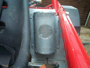
In the winter months the standard cooling system is fine, but in the heat of summer the engines get very hot when raced (The head casting reaches over 140’C). I have tried removing the thermostatic housing completely, but this makes little difference. The engine power output goes up as the engine becomes warmer, and seems best with a head temperature of around 110 – 120 ‘C. This is hard on any oil, so I would recommend running a good quality synthetic oil, such as used on turbo charged engines. With the airflow set to maximum, the draw from the fan inlet is very considerable, so a mesh with a good surface area is required to prevent grass and straw being drawn in.
![]()
Other worthwhile mods to your Blitz..
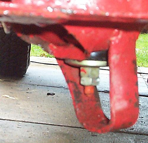
If your car is used heavily check the diagonal bar that leads down from the rear spring / shocker mounting point on each side as several cars have shown cracks in this area. To prevent this happening is best to remove the standard Fiat fuel tank, and weld a cross brace between the two turrets. A smaller tank will then need fitting.
Ensure the front gearbox mountings are new
 |
Rear engine mount and spring. Use at least two mounting plates welded together or 6mm steel plate. The springs also fail. A Ford Escort (FWD - CVH) gearbox mount can be made to fit the Blitz chassis point together with a 12mm bolt. Less compliant but the engine won’t fall out. In addition a mini front shock absorber can be linked between the fan housing and the chassis, that will stop the engine rocking to much. Thanks to Graham Prike of Blitzword for this idea |
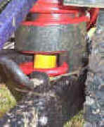
The rubber can break and the holes elongate and break. The rubber can be assisted by putting a small bolt through the centre to limit the stretch. Also shorten the gear stick to about 9” overall and fit a smaller gear knob. This reduced the whipping action over rough ground.
Gearbox ratios.
The 126 gearing does not do well off road, ether being flat out in second or not really pulling that well in third. Although both 5 and 6 speed gear clusters are available for the gearbox this is an expensive option and do not have syncromesh. A cheap way to get a close ratio box is to use the Fiat 500cc box as the final drive is lower. The 500 box however also has no sycromesh, so welcome to the world of the "crash box". This means careful matching of engine rev's when changing gear if you don't want a box of broken gears. The internal components are fairly light however, so this need not be too much of a trauma. The overall final drive ratio is about 10 % lower so the top speed is lower, but the ratios become closer and acceleration is much better. Third now pulls well on soft ground. Loss of top speed is made up for by the increased rev's available with a sports cam. The 500 cc box will not bolt straight in however, and will require stripping down to remove the drive shafts and bell housing. The 126 drive shafts must then be fitted to the 500 cc differential and the 126 bell housing fitted. Please read your Haynes manual on setting up the differential before undertaking this. Mark the bearing retainers left and right when removing the bell housing, and when be careful not to alter the settings for the inner drive shaft bearings. The load on these is pre set and the locked using a locking rings. Don't let these fall out or get altered. Officially as the bell housing is going to be a different casting, things should be set up from scratch, but I have had no problems as long as you are careful retaining the original settings.
Note: I have now gone back to the 126 gearbox as the lack of Syncromesh causes problems when racing.
Its worth fitting gas dampers to the rear, but use the standard ones on the front as the Blitz is much lighter than the original Fiat.
 |
Weld strong "u" brackets under the damper screw threads where they pass through the suspension link. Its easy to shear the threads off over rough ground otherwise. |
 |
Rear springs.The standard springs can be helped by using the Grayson spring assistors used for towing purposes. Part number is GE14 at about £8 each. Stocked by many motor shops or Demon Tweaks. These stop the suspension bottoming out.
|
Removal of the 2nd and 3rd spring (top downwards) greatly improves the front of the car A sharp eye needs to kept on the remaining springs as this increases the load on them. Don’t forget to add spacers to the remaining gap to prevent the leaf springs from slipping about. Note that the “clamps” allow the spring to pivot, so extra spacers must also pivot. The best way is to make a U shaped bracket, turned upside down over the lower clamp that cannot slip out, but can move.
Removing or changing the spacers from the top front wishbone to give some negative camber. This greatly improves the high-speed turn in on dirt but looses some of the straight-line stability at speed. Don’t forget to reset the toe in afterward (a couple of degrees toe in will assist the stability). The simplest way to set this is to place a straight rod about 4-5 ft long, level with the center of the wheel, (Old gallon oil cans are about the right height) and touching the tyre on both side. Do this for both wheels. The rods then project beyond the front of the car. Measuring the distance between the rods at the tyre end and the rod end will show if the wheels are parallel. Start with getting the front wheels parallel and then give them a little toe in. i.e. the front of the tyre faces slightly inwards. The official toe in is 5 -9 mm on the leading edge of the wheel rim between the two rims. This equates to approximately 3.5mm inwards per 12" (or 30cm) forward on the rod. This is considerable compared to many cars that are 1-2 mm.
Also see Fiat Racer
![]()

